Difference between revisions of "DIY Ninjas Section"
Jump to navigation
Jump to search
Realizator (talk | contribs) m (→CM1 support (how to change power mode)) |
Realizator (talk | contribs) m (→[One secret undeclared feature]) |
||
| Line 17: | Line 17: | ||
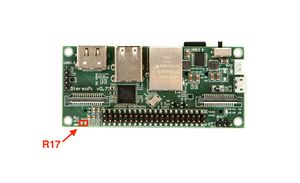
[[File:R17-stereopi-top.jpg|none|300px|R17 resistor StereoPi]] | [[File:R17-stereopi-top.jpg|none|300px|R17 resistor StereoPi]] | ||
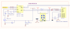
| − | == | + | ==Undeclared feature: usb client mode== |
| + | [[File:Usb-switch.png|none|300px|StereoPi usb switch]] | ||
==Device tree (DTS and dt-blob.bin)== | ==Device tree (DTS and dt-blob.bin)== | ||
Revision as of 16:15, 19 February 2019
Contents
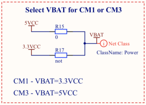
CM1 support (how to change power mode)

Compute Module 1 needs 5V VBAT power for kernel, and CM3/CM3+ needs 3.3V VBAT.
By default StereoPi tuned to provide 5V voltage for CM3 series support.
To change powering for CM1 you need:
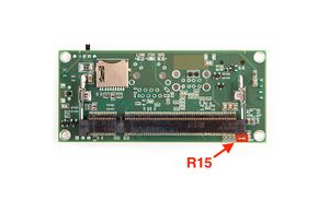
- Unsolder R15 (0 Ohm) resistor here:

- Solder R17 (0 Ohm) resistor or piece of wire here:

Undeclared feature: usb client mode

Device tree (DTS and dt-blob.bin)
Ready to use dt-blob.bin file:
Download mirror 1 (Wiki hosting)
Download mirror 2 (website hosting)
DTS source file
Download mirror 1 (Wiki hosting)
Download mirror 2 (website hosting)
Schematic of the StereoPi board
Original StereoPi schematic was created in Altium, and now we're trying to choose appropriate open source tool. At this moment we like KiCad. If you have some ideas what tool should we use for schematic, please let us know in out twitter here: