Difference between revisions of "StereoPi Specifications"
Jump to navigation
Jump to search
Realizator (talk | contribs) (Created page with "Features & Specifications Raspberry Pi Compatibility: Raspberry Pi Compute Module 1 Raspberry Pi Compute Module 3 Raspberry Pi Compute Module 3 Lite Raspberry Pi Compute Modul...") |
Realizator (talk | contribs) m |
||
| (8 intermediate revisions by the same user not shown) | |||
| Line 1: | Line 1: | ||
| − | Features & Specifications | + | == Features & Specifications == |
| − | Raspberry Pi Compatibility: | + | === Raspberry Pi Compatibility: === |
| − | Raspberry Pi Compute Module 1 | + | * Raspberry Pi Compute Module 1 |
| − | Raspberry Pi Compute Module 3 | + | * Raspberry Pi Compute Module 3 |
| − | Raspberry Pi Compute Module 3 Lite | + | * Raspberry Pi Compute Module 3 Lite |
| − | Raspberry Pi Compute Module 3+ 8 GB / 16 GB / 32 GB eMMC flash | + | * Raspberry Pi Compute Module 3+ 8 GB / 16 GB / 32 GB eMMC flash |
| − | Raspberry Pi Compute Module 3+ Lite | + | * Raspberry Pi Compute Module 3+ Lite |
| − | Dimensions: | + | |
| − | width x length: 90 mm x 40 mm | + | === Dimensions: === |
| − | height: 23 mm (standard edition) / 15 mm (slim edition) | + | * width x length: 90 mm x 40 mm |
| − | Video: | + | * height: 23 mm (standard edition) / 15 mm (slim edition) |
| − | input: two 15-pin CSI-2 camera connectors | + | |
| − | output: HDMI | + | === Video: === |
| − | Camera Support: | + | * input: two 15-pin CSI-2 camera connectors |
| − | Raspberry Pi camera V1 (OV5647 sensor) | + | * output: HDMI |
| − | Raspberry Pi camera V2 (Sony IMX 219 sensor) | + | |
| − | HDMI video capture module (single mode, on Toshiba TC358743XBG chip) | + | === Camera Support: === |
| − | Connectivity: | + | * Raspberry Pi camera V1 (OV5647 sensor) |
| − | GPIO: 40-pin classic Raspberry Pi header | + | * Raspberry Pi camera V2 (Sony IMX 219 sensor) |
| − | USB: 2 x USB Type-A, 1 x USB pin header | + | * HDMI video capture module (single mode, on Toshiba TC358743XBG chip) |
| − | Ethernet: RJ45 jack | + | |
| − | Storage: | + | === Connectivity: === |
| − | microSD card slot (accessed by Raspberry Pi CM3/3+ Lite) | + | |
| − | Power: | + | StereoPi '''Regular''' Edition: |
| − | 5 VDC input via two-pin header | + | |
| − | manual power switch | + | * GPIO: 40-pin classic Raspberry Pi header |
| − | Software: | + | * USB: 2 x USB Type-A, 1 x USB pin header |
| − | firmware update via Micro USB connector | + | * Ethernet: RJ45 jack |
| − | runs standard Raspbian | + | |
| − | + | StereoPi '''Slim''' Edition: | |
| − | + | ||
| + | * GPIO: no GPIO pins; soldering points for 40 GPIO | ||
| + | * USB: 1 x USB pin header; soldering points for 2 USB Type-A connector | ||
| + | * Ethernet: no RJ45 jack; soldering points for RJ45 jack | ||
| + | |||
| + | === Storage: === | ||
| + | * microSD card slot (accessed by Raspberry Pi CM3/3+ Lite) | ||
| + | |||
| + | === Power: === | ||
| + | * 5 VDC input via two-pin header | ||
| + | * manual power switch | ||
| + | |||
| + | === Software: === | ||
| + | * firmware update via Micro USB connector | ||
| + | * runs standard Raspbian | ||
| + | |||
| + | == StereoPi Pinout == | ||
| + | |||
| + | [[File:Stereopi-front-noted-alph-1280.png|none|800px|StereoPi Front Noted]] | ||
| + | |||
| + | [[File:Stereopi-top-noted-1280.png|none|800px|StereoPi Top Noted]] | ||
| + | |||
| + | A. boot mode jumper | ||
| + | |||
| + | B. camera 1 CSI-2 connector | ||
| + | |||
| + | C. micro USB (for firmware upload) | ||
| + | |||
| + | D. 5 VDC power connector | ||
| + | |||
| + | E. power switch | ||
| + | |||
| + | F. microSD slot | ||
| + | |||
| + | G. RJ45 Ethernet jack | ||
| + | |||
| + | H. dual USB Type-A connector | ||
| + | |||
| + | I. HDMI out | ||
| + | |||
| + | J. USB port pin header | ||
| + | |||
| + | K. camera 2 CSI-2 connector | ||
| + | |||
| + | L. 40-pin RPi GPIO header | ||
| + | |||
| + | M. RPi Compute SO-DIMM connector | ||
| + | |||
| + | == StereoPi GPIO pinout == | ||
| + | |||
| + | To preserve Pi hats compatibility (electrical and physical) we kept the original Raspberry Pi GPIOs but rotated them 180 degrees. | ||
| + | |||
| + | [[File:Stereopi-gpio.png|none|600px|StereoPi GPIO]] | ||
| + | |||
| + | == USB pins, power pins == | ||
| + | |||
| + | [[File:Stereopi-usb-power-pinout.png|none|600px|StereoPi USB pins, power pins pinout]] | ||
Revision as of 16:03, 27 May 2019
Contents
Features & Specifications
Raspberry Pi Compatibility:
- Raspberry Pi Compute Module 1
- Raspberry Pi Compute Module 3
- Raspberry Pi Compute Module 3 Lite
- Raspberry Pi Compute Module 3+ 8 GB / 16 GB / 32 GB eMMC flash
- Raspberry Pi Compute Module 3+ Lite
Dimensions:
- width x length: 90 mm x 40 mm
- height: 23 mm (standard edition) / 15 mm (slim edition)
Video:
- input: two 15-pin CSI-2 camera connectors
- output: HDMI
Camera Support:
- Raspberry Pi camera V1 (OV5647 sensor)
- Raspberry Pi camera V2 (Sony IMX 219 sensor)
- HDMI video capture module (single mode, on Toshiba TC358743XBG chip)
Connectivity:
StereoPi Regular Edition:
- GPIO: 40-pin classic Raspberry Pi header
- USB: 2 x USB Type-A, 1 x USB pin header
- Ethernet: RJ45 jack
StereoPi Slim Edition:
- GPIO: no GPIO pins; soldering points for 40 GPIO
- USB: 1 x USB pin header; soldering points for 2 USB Type-A connector
- Ethernet: no RJ45 jack; soldering points for RJ45 jack
Storage:
- microSD card slot (accessed by Raspberry Pi CM3/3+ Lite)
Power:
- 5 VDC input via two-pin header
- manual power switch
Software:
- firmware update via Micro USB connector
- runs standard Raspbian
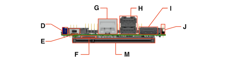
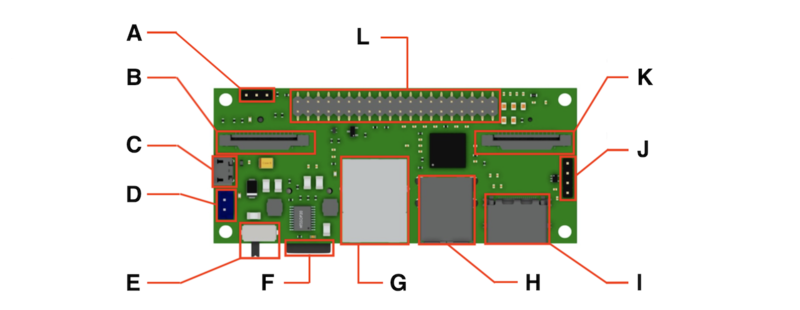
StereoPi Pinout


A. boot mode jumper
B. camera 1 CSI-2 connector
C. micro USB (for firmware upload)
D. 5 VDC power connector
E. power switch
F. microSD slot
G. RJ45 Ethernet jack
H. dual USB Type-A connector
I. HDMI out
J. USB port pin header
K. camera 2 CSI-2 connector
L. 40-pin RPi GPIO header
M. RPi Compute SO-DIMM connector
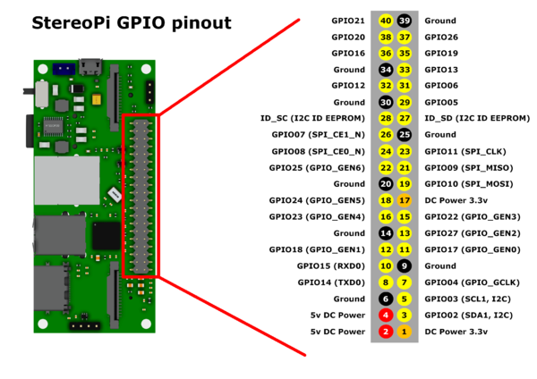
StereoPi GPIO pinout
To preserve Pi hats compatibility (electrical and physical) we kept the original Raspberry Pi GPIOs but rotated them 180 degrees.

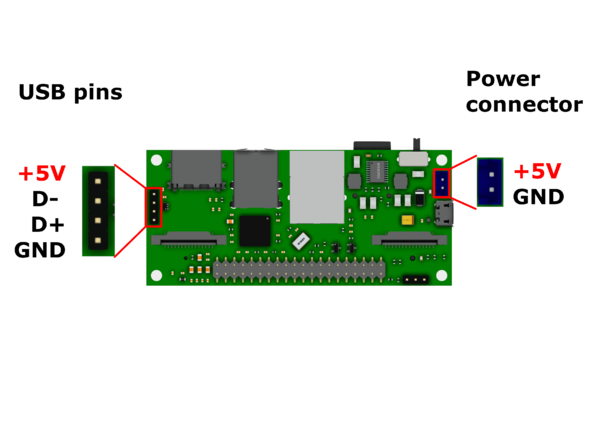
USB pins, power pins
