Difference between revisions of "StereoPi v2 Quick Start Guide"
Jump to navigation
Jump to search
Realizator (talk | contribs) m |
Realizator (talk | contribs) m |
||
| Line 1: | Line 1: | ||
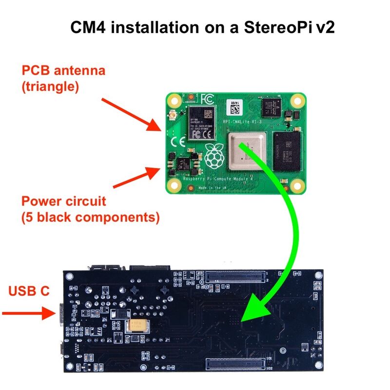
== How to install RPi Compute Module 4 (CM4) == | == How to install RPi Compute Module 4 (CM4) == | ||
| − | [[File:Cm4 installation stereopi v2.jpg|none| | + | [[File:Cm4 installation stereopi v2.jpg|none|800px|CM4 installation]] |
# Disconnect all external equipment and power. | # Disconnect all external equipment and power. | ||
| Line 8: | Line 8: | ||
# Put the CM4 module on the connectors and gently press the bottom until you hear a click. After that, do the same with the top part of the CM4. | # Put the CM4 module on the connectors and gently press the bottom until you hear a click. After that, do the same with the top part of the CM4. | ||
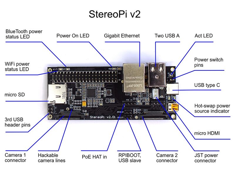
| + | == StereoPi v2 ports and connectors diagram == | ||
| + | |||
| + | [[File:StereoPi-v2-Annotaded.jpg|none|800px|StereoPi v2 ports and connectors diagram]] | ||
== Power switch == | == Power switch == | ||
| − | + | Install a jumper to the pins near the USB C connector. Please refer to the [[StereoPi v2 Quick Start Guide#StereoPi v2 ports and connectors diagram|ports and connectors diagram]]. | |
[https://youtu.be/Z3LX-8qM8HY YouTube video: Power Switch] | [https://youtu.be/Z3LX-8qM8HY YouTube video: Power Switch] | ||
Revision as of 13:43, 22 September 2021
Contents
How to install RPi Compute Module 4 (CM4)

- Disconnect all external equipment and power.
- Put the board upside down so that the USB C port is facing to the left.
- Take the CM4 module so that the triangle PCB antenna and the power circuit (a group of 5 black components) are faced to the left.
- Put the CM4 module on the connectors and gently press the bottom until you hear a click. After that, do the same with the top part of the CM4.
StereoPi v2 ports and connectors diagram

Power switch
Install a jumper to the pins near the USB C connector. Please refer to the ports and connectors diagram.
Note: advanced users can use external buttons or equipment to turn on/off the board.
How to connect power
We recommend using the UCB C power supply unit.
If the power jumper is installed, the board will boot as soon as you connect the power cable.
Advanced users: you can use either a USB C cable or the JST-EHR2 cable. You can also use them at the same time and hot-swap on the go. YouTube video: Hot Swap Power