Difference between revisions of "The Basics"
Realizator (talk | contribs) m |
Realizator (talk | contribs) m |
||
| Line 12: | Line 12: | ||
=== How to connect cameras === | === How to connect cameras === | ||
While connecting camera ribbons, the first step is PULLING black the fixator up 4-5 mm. After that insert camera ribbon by BLUE side to BLACK fixator. Check that the cable is fully inserted at a 90 degree angle. After that push the black fixator down to secure the ribbo | While connecting camera ribbons, the first step is PULLING black the fixator up 4-5 mm. After that insert camera ribbon by BLUE side to BLACK fixator. Check that the cable is fully inserted at a 90 degree angle. After that push the black fixator down to secure the ribbo | ||
| + | |||
| + | === How to connect power === | ||
| + | '''Important.''' | ||
| + | Please let me dispel the myth: The MicroUSB on StereoPi is not for power as with the classic RaspberryPi. | ||
| + | |||
| + | The MicroUSB on StereoPi is intended for uploading the eMMC firmware. Connecting the MicroUSB to StereoPi will place StereoPi in a special mode. There’s also one backdoor feature the MicroUSB permits, [https://wiki.stereopi.com/index.php?title=DIY_Ninjas_Section#Undeclared_feature:_usb_client_mode usb-client mode]. In this mode LAN9513 chip is physically disconnected from CM USB, so '''LAN and USB are disabled'''. | ||
| + | |||
| + | |||
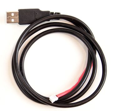
| + | * There is a two-pin white connector on board for connecting power supply. Included in your kit is a USB A power cable, with a special connector to power the StereoPi. | ||
| + | [[File:Stereopi-usb-power-cable.jpg|none|400px|StereoPi USB power cable]] | ||
| + | |||
| + | |||
| + | |||
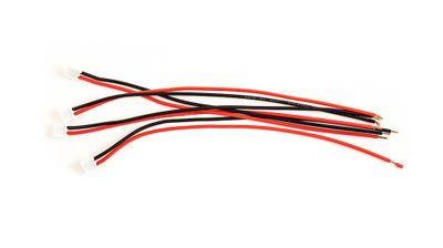
| + | * If space is tight inside your robot or enclosure, another cable, like this one, can be used to power the StereoPi instead of the USB cable. | ||
| + | [[File:Stereopi-power-cable.jpg|none|400px|StereoPi power cable]] | ||
Revision as of 13:19, 25 April 2019
Contents
The Basics
How to insert RPi Compute Module
While inserting Compute Module 3(CM3) in to the SteroPi, first insert it in the SO-DIMM connector at a 45-degree angle and firmly press down until you hear a “click”. If you will not insert it correctly (with a 45 degree angle), you may still hear a “click”, but some CM3 contacts may not make contact with the SO DIMM connector pins. If the device is powered up in this configuration, it will either will not boot, or will die a painful death! So, do yourself a favor and remove and install the StereoPi with a 45 degree angle!
How to prepare Raspbian image
You may download latest Raspbian image and write it on MicroSD card. To add support of both cameras you need just to put dt-blob.bin file in a “boot” partition.
This dt-blob.bin file is available here in our Wiki
You can also use our S.L.P. Raspbian image
How to connect cameras
While connecting camera ribbons, the first step is PULLING black the fixator up 4-5 mm. After that insert camera ribbon by BLUE side to BLACK fixator. Check that the cable is fully inserted at a 90 degree angle. After that push the black fixator down to secure the ribbo
How to connect power
Important. Please let me dispel the myth: The MicroUSB on StereoPi is not for power as with the classic RaspberryPi.
The MicroUSB on StereoPi is intended for uploading the eMMC firmware. Connecting the MicroUSB to StereoPi will place StereoPi in a special mode. There’s also one backdoor feature the MicroUSB permits, usb-client mode. In this mode LAN9513 chip is physically disconnected from CM USB, so LAN and USB are disabled.
- There is a two-pin white connector on board for connecting power supply. Included in your kit is a USB A power cable, with a special connector to power the StereoPi.
- If space is tight inside your robot or enclosure, another cable, like this one, can be used to power the StereoPi instead of the USB cable.

